
When businesses need reliable metal components, they rarely just need a single process. Most projects involve a sequence of steps: cutting sheet metal to profile, forming it into shape, welding components together, and finishing them so they are ready for use.
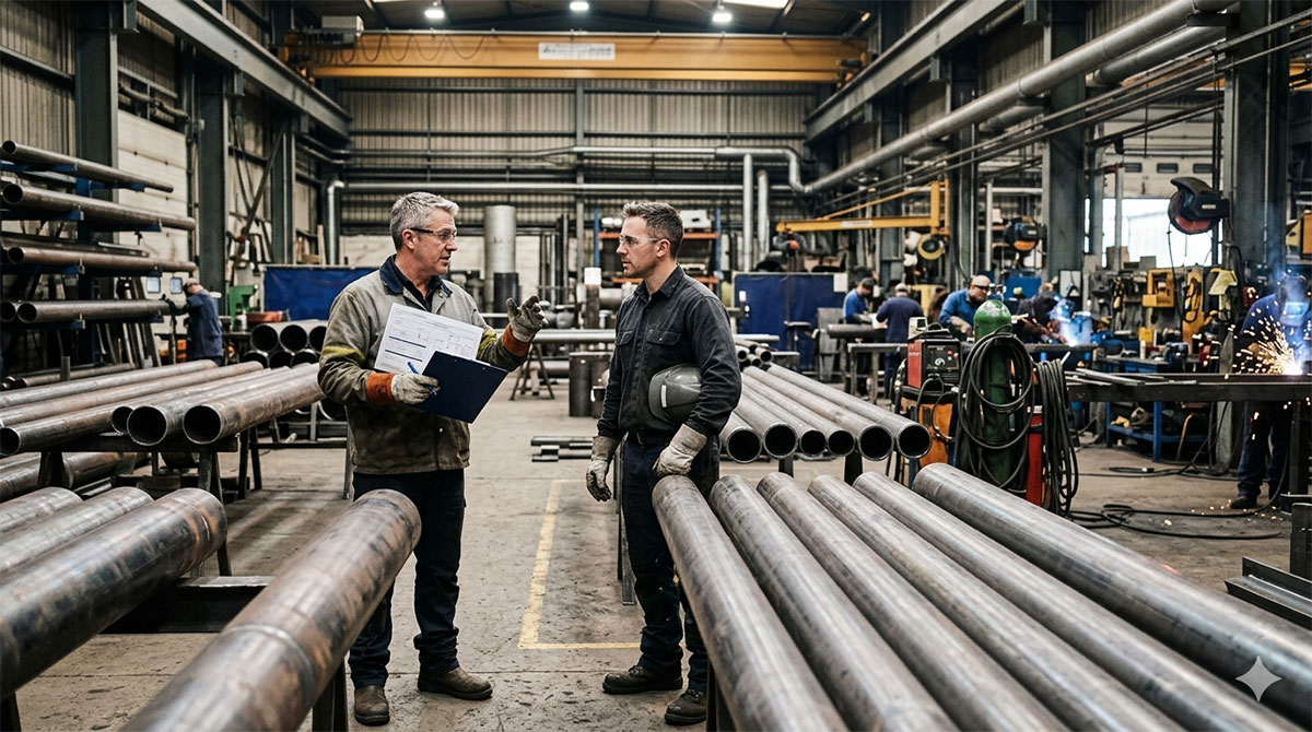
For buyers, engineers, maintenance managers and product designers, the challenge often isn’t the fabrication itself, but rather it’s the coordination between multiple suppliers. One company cuts the parts, another folds them, a third handles welding or finishing. Each handover introduces the potential for delays, tolerance issues, and the all-too-familiar response: “that didn’t happen here.”
An integrated sheet metal fabrication workshop removes those risks. When cutting, CNC folding and welding are managed by the same team, components move through a controlled process from flat sheet to finished assembly in a faster, more accurate way, and with clear accountability throughout.
What “Sheet Metal Fabrication” Really Means (And What Counts as “Under One Roof”)
Cutting, Forming and Assembling – One Joined-Up Process
In practical terms, sheet metal fabrication is the process of turning flat metal sheet into a finished component. This typically involves three core stages:
- Cutting the sheet to shape
- Forming or bending it into the required geometry
- Assembling parts through welding or mechanical fasteners
The phrase “under one roof” means these processes happen within the same facility and under the control of the same engineering team. Instead of passing parts between suppliers, one workshop manages datum points, tolerances, fit-up and quality control throughout the entire fabrication process.
Why Integrated Fabrication Matters for Projects
When multiple suppliers are involved, every handover introduces potential problems. A bend might not match the design intent of the cut profile, or weld preparation may require unexpected rework. Small deviations at each stage can accumulate into larger tolerance issues during final assembly.
Integrated fabrication avoids this. With a single team overseeing the entire process, adjustments can be made quickly, prototypes can be refined without restarting the supply chain, and responsibility remains clear. For companies developing custom metal fabrication or sheet metal prototyping, this joined-up approach significantly reduces both time and risk.
Step 1: Specification and Design Preparation (The Bit That Saves Money Later)
What to Decide Before You Cut Metal
Successful fabrication begins long before the first sheet reaches a machine. Early decisions shape cost, manufacturability and durability.
Key considerations include material selection – typically mild steel, stainless steel or aluminium – along with thickness, quantities and the intended operating environment. A component installed indoors may have very different requirements from one exposed to coastal weather or industrial chemicals.
Tolerances are another important factor. Specifying extremely tight tolerances where they are not necessary can significantly increase manufacturing cost. Identifying which dimensions are critical and which can remain flexible keeps fabrication efficient.
Designing for Fabrication (DFM) – Quick Wins
Designing parts with fabrication in mind can prevent many common issues. Practical considerations include maintaining appropriate hole-to-edge distances, ensuring slots and holes match realistic cutting limits, and incorporating bend relief where parts will be folded.
Features such as tab-and-slot joints can simplify assembly and improve alignment during welding. For new designs or complex components, sheet metal prototyping is often the most effective way to confirm geometry and performance before committing to a full production run.
Step 2: Industrial Cutting (Laser Cutting for Accuracy and Repeatability)
Why Laser Cutting Is the Go-To for Sheet Work
Modern fabrication relies heavily on CNC laser cutting for sheet metal components. Laser cutting produces clean edges, precise profiles and consistent parts, making it suitable for both prototypes and batch production.
Because the cutting path is controlled digitally, designs can be reproduced with high repeatability. Multiple parts can also be nested efficiently within a sheet, reducing waste and improving material utilisation.
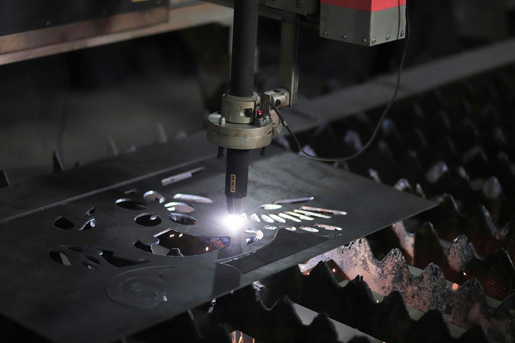
What to Share for Faster Quoting and Fewer Revisions
Clear information at the quoting stage helps avoid unnecessary revisions later. The most useful files are typically DXF or STEP files, along with material grade, thickness, quantities and any finishing requirements.
Common design issues that slow production include extremely small holes, sharp internal corners, and features placed too close to bends. Addressing these details early ensures smoother fabrication and predictable results.
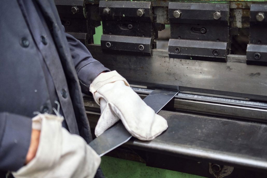
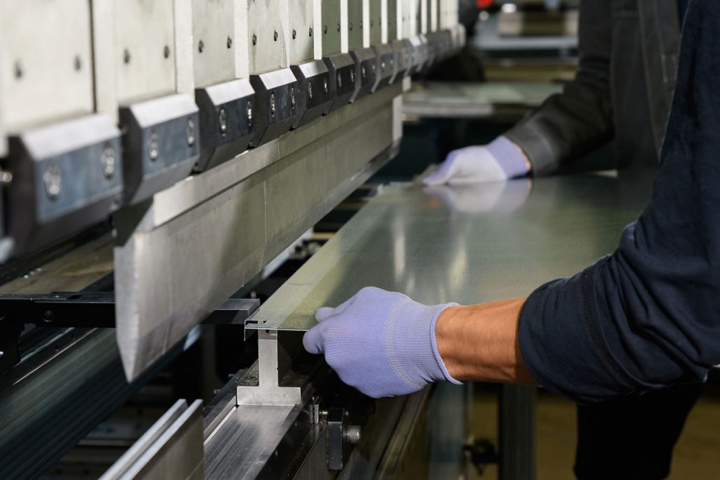
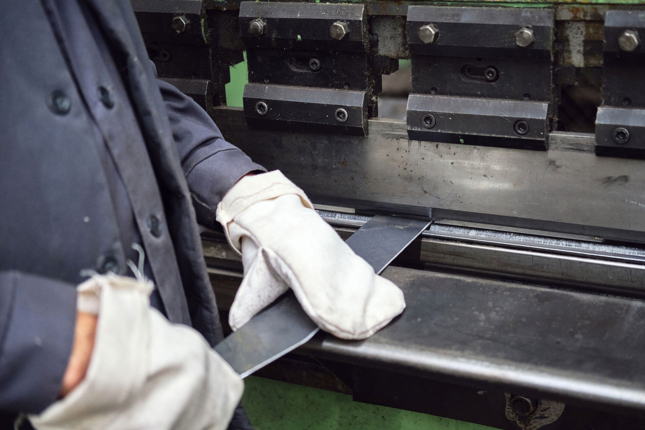
Step 3: Sheet Metal Folding (From Flat Parts to Functional Components)
CNC Folding Basics (What Folding Actually Controls)
Once sheet components are cut, they are shaped using CNC press brake bending. Folding determines the final geometry of the part by controlling bend angles, inside radii and bend allowances.
Material behaviour must also be considered. Metals exhibit “springback”, meaning they partially return toward their original shape after bending. Modern CNC press brakes compensate for this, ensuring bends remain consistent across production runs.
Folding accuracy directly influences downstream processes. If bends are incorrect, parts may not align properly during welding, which slows assembly and increases rework.
Typical Folding Features That Make Assemblies Easier
Folding is also used to add strength and functionality to sheet metal components. Simple features such as return flanges increase stiffness, hems improve edge safety, and formed channels create structural rigidity without adding extra material. These design details help ensure assemblies fit together efficiently and maintain their shape during service.
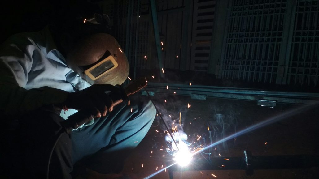
Step 4: Welding and Fabrication (Assembling Parts That Stay True)
Choosing the Welding Approach
Once components are cut and formed, they move into welding and fabrication. The welding process selected depends on material type, structural requirements and final appearance.
MIG welding is commonly used where strength and productivity are priorities, particularly with mild steel fabrication. TIG welding offers greater control and a cleaner finish, making it suitable for stainless steel or precision assemblies. Proper weld preparation and accurate fit-up are essential. Clean laser-cut edges and consistent folds help reduce welding time and improve overall build quality.
Controlling Distortion and Keeping Assemblies Square
Heat from welding can introduce distortion if not managed carefully. Experienced fabricators use techniques such as controlled tack sequencing, fixtures and jigs to maintain alignment throughout the welding process. When welding and assembly are handled in the same workshop as cutting and folding, any adjustments can be made immediately, ensuring components remain square and meet design tolerances.
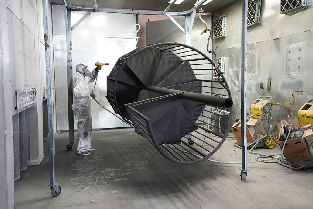
Step 5: Finishing (Making Parts Durable, Safe and Ready for Use)
Mechanical Finishing Before Coatings
Before any protective coating is applied, components typically undergo mechanical finishing processes. These may include deburring, edge breaking, grinding or linishing – an abrasive machining process used to smooth and refine surface finishes. These steps improve both safety and appearance, removing sharp edges and ensuring components are ready for handling or further processing.
Protective Finishes for Different Environments
Surface finishing protects fabricated components and improves durability. The appropriate finish depends on the operating environment. For outdoor structures or industrial installations, powder coating, paint systems or galvanising may be used to prevent corrosion. Stainless steel assemblies may require polishing or brushed finishes where hygiene or appearance is important.
Architectural metalwork commonly combines fabrication processes such as laser cutting, folding, welding and powder coating to produce durable, visually consistent components.
Prototyping to Production: How Integrated Fabrication Speeds Iteration
Fast Prototype Loops Without Starting Over
When fabrication processes are integrated, prototype development becomes far more efficient. Adjustments to cut files, bend geometry or weld sequencing can be made quickly without restarting the supply chain. This allows engineering teams to refine designs through rapid iteration and achieve the desired outcome faster.
When to Move to Batch Production
Once a prototype is approved, moving to production requires consistent documentation. Revision-controlled drawings agreed tolerances and inspection requirements ensure parts can be reproduced accurately in future runs. Packaging and delivery arrangements also become important when quantities increase, ensuring components arrive safely and ready for installation.
What Burnhouse Typically Fabricates
Burnhouse Engineering produces a wide range of fabricated components, including:
- Access platforms and working-at-height structures
- Staircases and balustrades
- Control panel housings and sheet metal enclosures
- Decorative and architectural metalwork
These projects support clients across multiple sectors, including industrial processes, aerospace supply chains, marine applications, food and drink production, manufacturing and the alternative energy sector.
Why “Local” Matters: Lead Times, Logistics and Project Support
Burnhouse Engineering is based in Beith, Ayrshire, KA15, near Glasgow, supporting projects throughout Scotland and across the UK.
Working with a local fabrication partner offers practical advantages. Site visits are easier to arrange, collections and deliveries are quicker, and design changes can be addressed without long delays. When fabrication issues arise (as they often do during projects!), being able to get experienced engineers on the job quickly makes a significant difference.
How to Get a Fast, Accurate Quote
If you need sheet metal fabrication, providing clear information at the start helps ensure accurate pricing and faster turnaround.
Include the following in your enquiry:
- Part files (DXF + PDF drawing, or STEP where relevant)
- Material, thickness and grade
- Quantity required (prototype or batch production)
- Any critical tolerances
- Finish requirements (raw, deburred, powder coated, etc.)
- Delivery postcode and required deadline
Send your drawings to Burnhouse Engineering and our team will advise the most efficient cut-fold-weld route for your project, balancing cost, lead time and manufacturing practicality.
Recent Blogs
-

How to Get a Faster Fabrication Quote
-
ISO 3834, WPS, PQR and WPQ Explained for Buyers
-
What EN 1090 Means for Structural Steelwork Buyers
-
Sheet Metal Fabrication: Cut + Fold + Weld Under One Roof (And Why That Matters)